Thursday, 10 December 2020
How to Calibrate a Float Level Sensor with a 4-20mA Current Loop Output

In this post, Intempco will teach you how to calibrate a float level sensor in three simple steps. For a visual guide, watch Intempco’s video tutorial.
What is a Float Level Sensor?
A float level sensor is used to detect the liquid level of a fluid. The most ideal scenario is a fluid inside a tank, but it can also be used in plenty of other applications. It is suited for industrial use and can withstand harsh environments. A float level sensor can be used to control the height of the fluid for safety, practical, or economical purposes.
How Does a Float Level Sensor Work?
The sensor probe acts as a path for the float to travel up and down due to the buoyancy of the fluid. Inside the float is a sealed magnet, which triggers a location specific reed switch depending on its location. Each reed switch represents a different location and the electrical circuitry will send and receive the appropriate resistance depending on which reed switch is active. Once the sensor sends the resistance, then the transmitter can proportionally convert that to a 4-20mA signal. A 4-20mA current signal transmitter uses a small amount of current from the loop to function, but as it is significantly less than 4mA, it has no effect on the total measurement. There are 4 connections from the sensor to the transmitter and the wire colors are printed on the side of the transmitter. It is always best to refer to the user manual of the transmitter for wiring.
How to Calibrate a 4-20mA Current Loop Transmitter
For our demonstration, we are using an Intempco Float Level sensor similar to the LFT42 Level Float Sensor.
SETUP
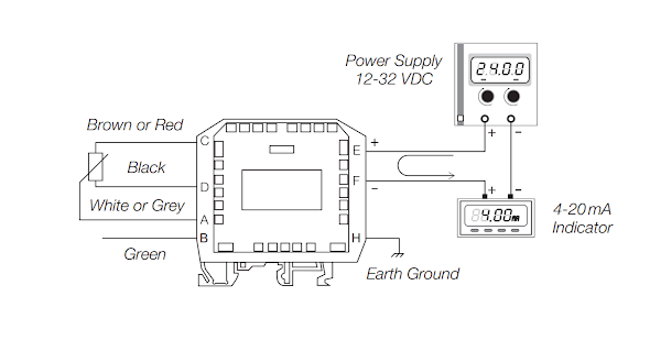
The transmitter is hooked up to a variable power supply, with an ammeter in series with the circuit. Attached to the sensor head is the transmitter that converts that resistance into a 4-20mA current signal. To ensure proper setup and calibration of the probe a zero-point and span correction is required.

Step 1: Connect the Positive and Negative Loops
Use a precision ammeter for proper calibration. Connect the positive of the supply to the positive input of the transmitter. This is “Loop Positive”.
Then, connect the output of the transmitter, “Loop Negative”, to the input of the ammeter. Next, connect the negative of the ammeter to the negative of the supply in order to complete the circuit.
Step 2: Adjust the Zero-Point (Z)
The “Z” point stands for “Zero-Point” or in other words the lowest possible reading. With a 4-20mA signal, the Z-point is 4.00mA.
To begin, place the float at the lowest point on the sensor probe. You should not have to press hard, just let it sit on the bottom. The ammeter will give a reading that will be very close to 4.00mA, but may not be 4.00mA. It is your job to adjust the value to bring it to 4.00mA
To adjust the current reading, we will be adjusting a potentiometer. The adjustment potentiometer is located on the din rail transmitter, and is labeled “Z”, as in “zero-point”.
To adjust the zero point (Z), use a small flat head screwdriver and turn it either clockwise or anti-clockwise depending on whether your signal needs to be increased or decreased. Adjust it until you reach 4.00mA.
Step 3: Adjusting the Span (S)
The next step is to adjust the span (S). By doing this, you are correcting the full range of level readings. To do this, move the float to the top position; and allow the ammeter to stabilize. The reading should be very close to 20.00mA. Adjust the (S) potentiometer until it is exactly 20.00mA.
Now, return the float to the zero position, and ensure that the indicated current level is 4.00mA. You might have to go back and forth a few times until both points are correct.
After Calibration
Once the device is calibrated, it will not drift. The float sensors use magnetic reed switches that are designed for that they cannot drift at all.
The only possibility of drift is within the 4-20mA transmitter, and by using a quality Intempco transmitters that drift risk can be minimized. This will ensure the reading will stay stable.
Looking for a reliable and durable solution to detect liquid levels in various applications?
Whether you need to monitor fluid levels in a tank or other industrial settings, a float level sensor is an ideal choice. With its ability to withstand harsh environments, it can help ensure safety, practicality, and economy in your operations. Plus, it can be used to control the height of the fluid to meet your specific needs. Choose a float level sensor for your liquid level detection needs and enjoy accurate and reliable performance.


